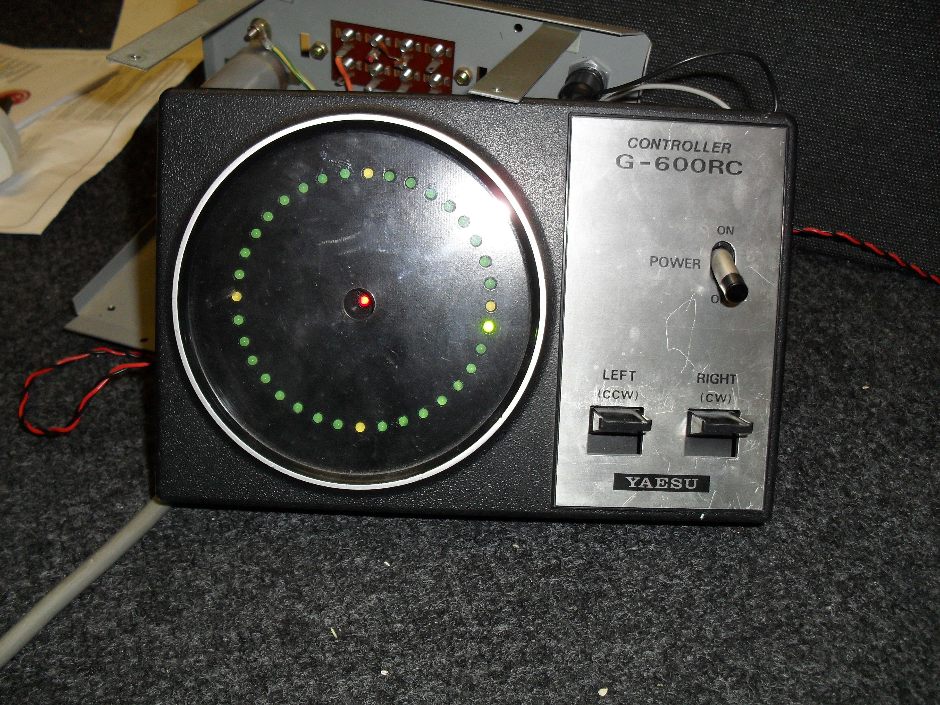
The display mechanism in my trusty Yaesu G600RC ( well it is 23 years old ) finally gave up after repeated rubber band changes so after a brief thought as to how to replace it . I came up with the idea of using LED's and a bargraph chip or two .The usual web search was made it came up with a design by OK2KKW ( LINK) from his basic design I redrew it to fit the existing fixing points in the controller case along with changing the values of the calibration resistors to " Fit " the existing variable resistor located in the rotator head unit .The PCB was designed so that the " End stop " could be set for any one of the 4 major compass points ( N,S,E,W ) as due to being located on the west of Europe ( QTH Loc. IO92AL ),I had decided to put my endstop in the west due to the needs of Auroral working on VHF ( I found out the hard way with the DX always the wrong side of the endstop ! ).
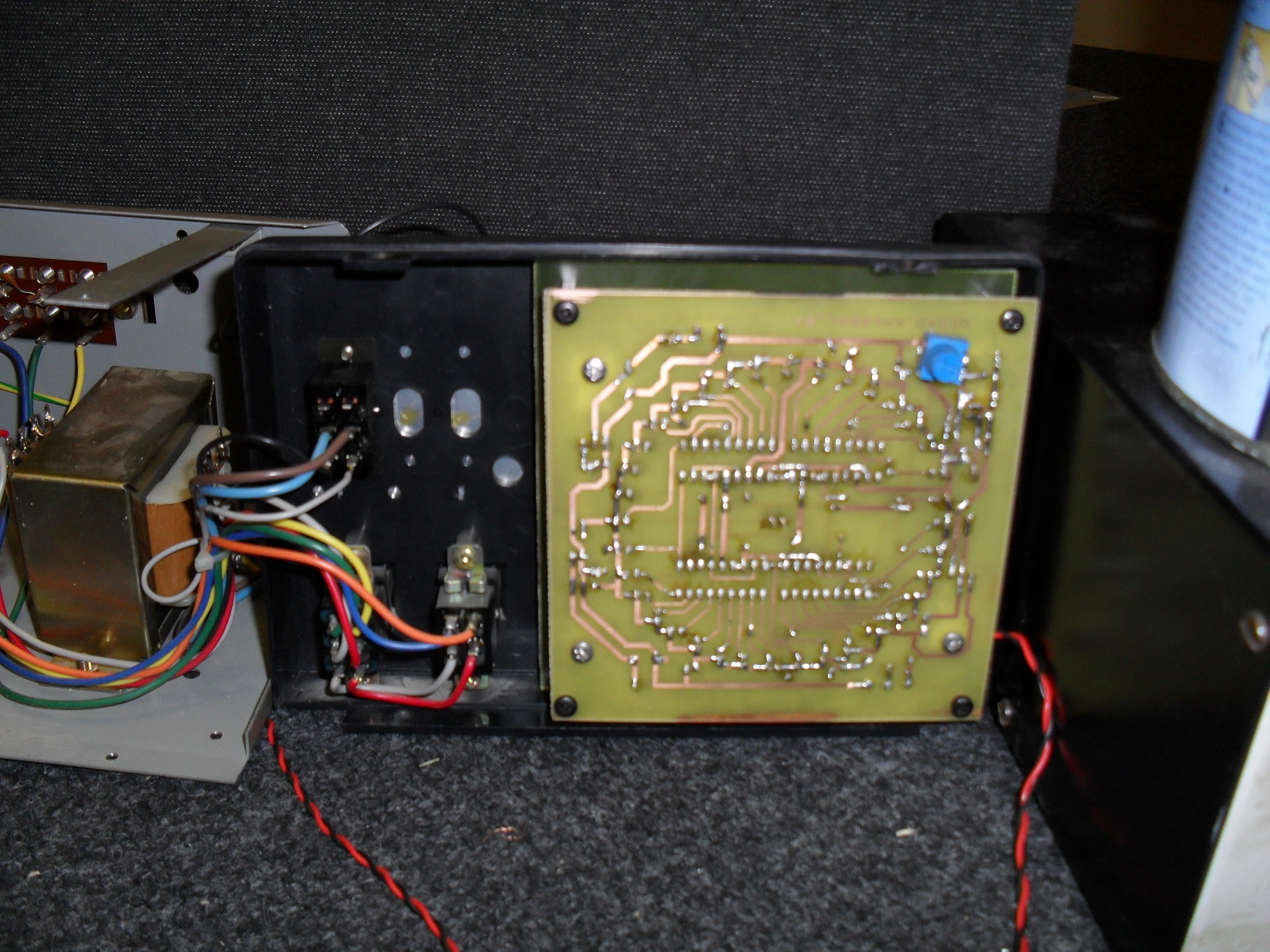
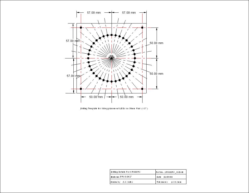
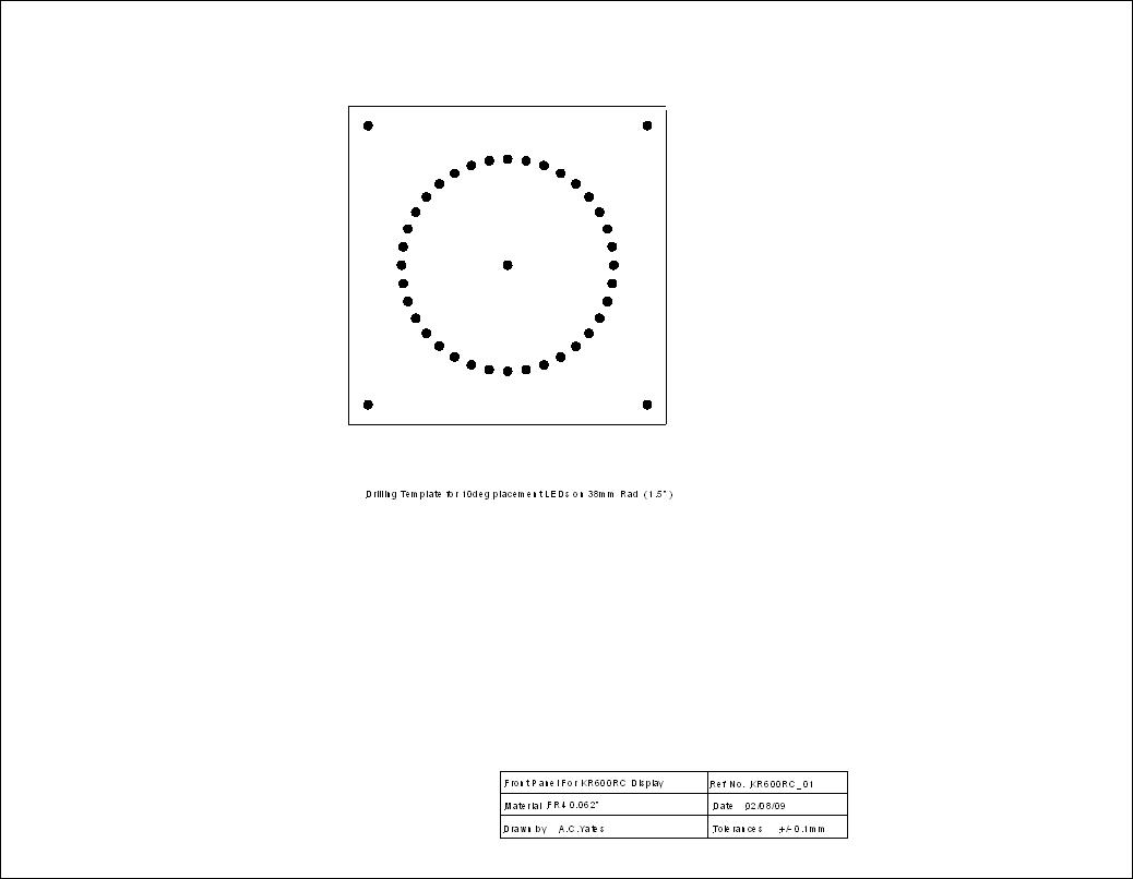
The display module comprises a double sided PCB for the electronics , with a single sided PCB forming the display panel spaced out using standard pillars ( M3 thread x 18mm long ) the pillars are screwed into the original holes ( you may need to tap these out ) in the front panel these hold the display panel in place , the electronics PCB is then secured to these pillars forming a nice compact assembly which should last a long time ( at least as long as the old motorised pointer ) .The electronics PCB is double sided so the " Top " copper ( mirrored ) must be used to produce a board using the precoated PCB material available from most suppliers simply making an envelope to put the board in .For the bargraph IC's you must use the more expensive " Turned pin " style of IC socket as many of the IC pins are use for the through board links ( It's cheaper than a PTH pcb ).The front panel to hold the LEDs was simply drawn up using a CAD package this gave a more accurate 10deg spacing than was possible using the PCB drawing package , then this was etched on single sided PCB material and spray painted to suit .The most tedious part of the job being the calibration to set the rotator end points , a selection of photo's were taken during intial testing of the PCB and it's fitting in to the G600RC's case before the final calibration setting the clockwise & counter clockwise end points .
The circuit uses 4 LM3914 bargraph IC's to give 36 LEDs at a 10 degree resolution the voltage to drive the display IC's is obtained from using an LM317 voltage regulator to generate a stabilised output using the rotator's variable resistor to set the voltage along with any resistive losses within the rotator cables , the two end points being set by ten turn trimpots located on the main PCB this means using SIDE adjust versions to calibrate the unit when assembled otherwise there is a risk that the LED's will become misaligned during the calibration period . During assembly of the PCB , All the components with the Exception of the LED's can be soldered in place , the LED's being fitted loosely in the board ,the pillars then fitted along with the display front panel. Then the LED's are pushed through to align in the holes then soldered to the PCB , the topside joints can be made where neccesary by removing the front panel , having first soldered them on the bottom copper layer to hold them in place.
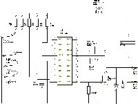
The circuit & PCB artworks are available as PDF's from the links below. ( Note the blue pot being used to replace the pot located on the rotator head unit during calibration .)
Circuit diagram of " Modified " OK2KKW rotator display
Silk layer for component placement
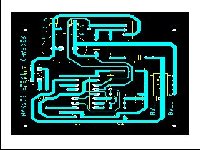
Topcopper artwork
Top copper artwork ( Mirrored )
Bottomcopper artwork
Display Front panel drawings and artworks ( linked to PDF's )
Back to Amateur Radio Projects
This page last updated 29th Oct 2009